
| Version 5 (modified by , 8 years ago) (diff) |
|---|
Electrical Overview
Robots need power and most robots draw their power from an electrical battery.
Batteries
 Batteries have two electrical terminals and chemicals between them. The terminals and chemicals are chosen so that they can react chemically, for the reaction to work, one terminal needs to lose electrons and the other needs to gain them. So when electrons can move from one terminal to the other, the chemical reaction proceeds. Normally, the battery terminals are separated by air which resists the flow of electrons, but if the terminals are connected together with a wire or other material that allows electrons to flow, the reaction proceeds as long as electrons flow from one terminal to the other.
- The battery terminal that supplies electrons is called the negative terminal and is usually marked with a black color or '-' sign.
- The battery terminal that consumes electrons is called the positive terminal and is usually marked with a red color or '+' sign.
Voltage
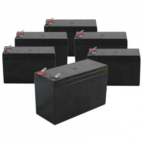
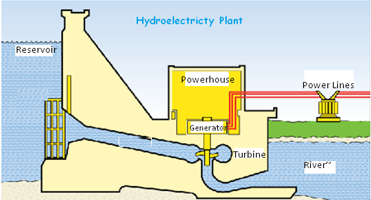
The difference in electrical potential between the two terminals is measured in units of Volts (named after Alessandro Volta). Voltage is *potential* energy, like the reservoir/lake behind a hydroelectric dam; no work is being done if the water isn't flowing, but you can measure the pressure the water is exerting on the dam. It's important to recognize that voltage is just a potential, no work is being done by voltage, it represents a difference in charge, the strength of attraction between two opposite charges. There are many different types of batteries that use different types of chemical reactions to generate that charge potential difference. The oldest type of battery, and the one we still use on our robots, is the lead-acid battery which uses lead terminals and sulphuric acid. These batteries produce 2 volts per cell; if you put 6 of them together in sequence, you can get 12 volts.
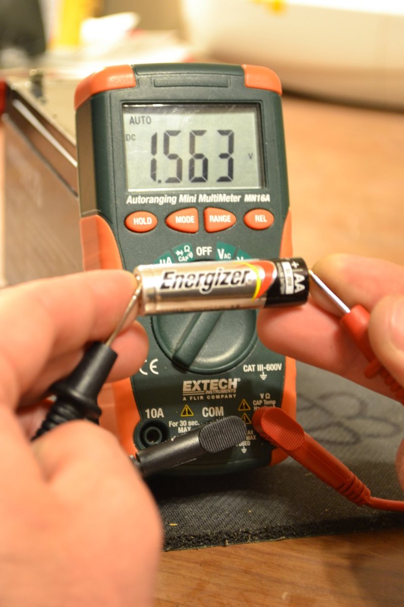
You can use a meter called a voltmeter or a multimeter to measure the amount of voltage "pressure" a battery exerts.


- Exercise: Use a multimeter to measure the voltage of a battery:
- Turn the multimeter on and move the range selector knob to DC Volts (often shown as DCV or a dashed line over a solid line)
- Plug the black wire into the hole labeled COM
- Plug the red wire into the hole labeled V/mA/...
- Touch the other end of the black wire to the negative (-) terminal of the battery
- Touch the other end of the red wire to the positive (+) terminal of the battery
- The multimeter will display the battery voltage
- What happened: the electrical pressure, (the difference in positive vs. negative charge) between the two terminals is measured by the multimeter and displayed. Virtually no energy is consumed from the battery in making this measurement.
Current
 When electrons are allowed to flow between the positive and negative battery terminals, we have a *circuit* and the battery's chemical reaction proceeds (until the chemical reaction is complete). The number of electrons flowing between the terminals is called "Current" and is measured in Amperes aka Amps (named after André-Marie Ampère. The number of electrons flowing depends on how many electrons the battery can supply (how fast the chemical reaction can proceed) and the nature of the path carrying the electrons from one terminal to the other. You can measure current using your multimeter in the next section.
Power
When there is pressure and flow, you can do work. Like water under pressure flowing through a dam and turning a hydroelectric turbine or water wheel, electrons flowing through a circuit can do work. Examples include lighting a bulb, turning a motor, or powering a computer.
- Exercise: light a bulb with a battery
- Connect one end of an alligator clip jumper wire to the negative (-) terminal of the battery; this will be called the negative wire.
- WITHOUT letting it touch the negative wire, connect one end of another alligator clip jumper wire to the positive (+) terminal of the battery; this will be called the positive wire.
- Connect the other end of the negative wire to one terminal on a bulb
- Connect the other end of the positive wire to the other terminal on a bulb
- Let there be light!
- What happened: the two jumper wires and the wire filament in the bulb provide a path for the electrons to flow from the negative battery terminal to the positive battery terminal, creating a complete circuit. As the electrons flow through the circuit, the resistance they encounter as they push their way through the bulb's filament cause it to get hot, glow, and emit light.
The power used to light the light or turn a motor is is measured in Watts (named after James Watt) and is a function of voltage (the pressure from the battery) and current (the number of electrons flowing); specifically
Watts = Amps * Volts
- Exercise: use a multimeter to measure the current flowing through the light bulb circuit
- Turn the multimeter on and move the range selector to DC Amps (usually marked with an A)
- Plug the black wire into the hole labeled COM
- Plug the red wire into the hole labeled 10A
NOTE: this is IMPORTANT; if you try to measure much current with the red wire in the V,mA,... hole, you will blow the fuse in your multimeter and potentially damage it.
- disconnect the negative alligator wire from the bulb and connect it to the black multimeter wire
- connect the red multimeter wire to the bulb terminal that had previously been connected to the black wire
- observe the amount of current flowing in Amperes on the multimeter display
- What happened: The multimeter is now part of the circuit; the electrons flowing through the multimeter and the bulb as they proceed from the negative battery terminal to the positive terminal. The multimeter measures the number of electrons flowing through it.
- Exercise: use a multimeter to measure the current flowing through a DC motor
- Unplug the bulb from the circuit above
- Connect the positive wire (alligator jumper wire connected to the positive battery terminal) to one of the motor wires or terminals
- Connect the multimeter red wire to the other motor wire or terminal
- The motor spins!
- observe the amount of current flowing in Amperes on the multimeter display
- What happened: Just as water turning a hydroelectric turbine in a dam converts some of the mechanical turning energy into electrical energy (flowing electrons), the DC motor converts some of the energy from electrons flowing through it into mechanical rotational energy. The DC motor contains coils of wire that allow electricity to flow from one terminal to the other (and cause the motor to spin in the process). The work the motor can do is proportional to the power (voltage * current) of the electrons flowing through the circuit.
- Exercise: make the motor change directions by reversing the direction of current flow
- Disconnect the positive wire from the motor terminal it is connected to, noting which terminal that is (we'll call it P)
- Disconnect the multimeter red wire from the other motor terminal (we'll call it N)
- Reverse the connections so the positive wire connects to terminal N and the multimeter red wire connects to terminal P
- The motor spins the other direction!
- What happened: The direction the DC motor spins is determined by the direction of the flow of electrons through it.
Resistance
Our circuits have consisted of a battery, wires to carry electrons to and through a load like a bulb or motor. The load presents resistance to the flow of electrons and when the pressure (voltage) of the battery pushes the electrons through the load, some of that work is converted into other forms of work energy (heat, light, rotational force, etc.). The amount of work done by the electrons flowing is proportional to the resistance presented:
   Watts = Volts * Amps
   Volts = Amps * Resistance
   Watts = Amps * Amps * Resistance
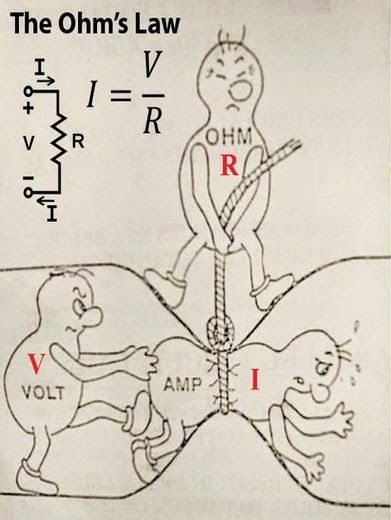
Resistance is measured in Ohms (named after [https://en.wikipedia.org/wiki/Georg_Ohm Georg Ohm). The relationship between voltage, current, and resistance is fixed (i.e. the amount of current that flows is determined by the pressure being applied and the resistance to that pressure) and is defined as "Ohms Law":
Volts = Amps * Resistance
You can measure resistance using your multimeter.
- Exercise: measure the resistance of various loads
- Turn your multimeter on and the range selector to Ohms (often shown with the Greek letter Omega)
- Plug the black wire into the hole labeled COM
- Plug the red wire into the hole labeled V/mA/Ohms...
- Touch the black wire to one of the load wires/terminals
- Touch the red wire to the other load wire/terminal
- Observe the resistance measurement on the multimeter display
- What happened: The multimeter contains a small battery; it measures the current that flows from its internal battery through the load and uses Ohms law to determine the resistance.
Attachments (10)
-
Cen-Tech_Multimeter.jpg (161.3 KB) - added by 8 years ago.
Cen-Tech Multimeter
-
UT136B.jpg (50.3 KB) - added by 8 years ago.
UT136B Multimeter
-
sla_battery.jpg (18.8 KB) - added by 8 years ago.
SLA Battery
-
dam_diagram.png (96.0 KB) - added by 8 years ago.
Dam block diagram
-
measure_AA.jpg (140.2 KB) - added by 8 years ago.
Measure AA battery voltage
-
measure_SLA.jpg (181.7 KB) - added by 8 years ago.
Measure SLA voltage
-
static_shock.jpg (3.9 KB) - added by 8 years ago.
Static shock
-
ohms_law.jpg (32.8 KB) - added by 6 years ago.
Ohm's Law
-
YoungFrankenstein.jpg (21.7 KB) - added by 6 years ago.
Young Frankenstein
-
tim1.jpg (151.9 KB) - added by 5 years ago.
Current Waterfall
Download all attachments as: .zip