
Materials Needed
- You will need: A photoresistor, an arduino, an LED, and wires.
- For this project, you can only use TinkerCAD, as the Arduino kits do not have any photoresistors.
Steps
- As the name suggests, a photoresistor is a resistor of some kind, except that it can change resistance. A photoresistor is called a variable resistor, because it’s resistance changes, and in this case, changes depending on the amount of light around.

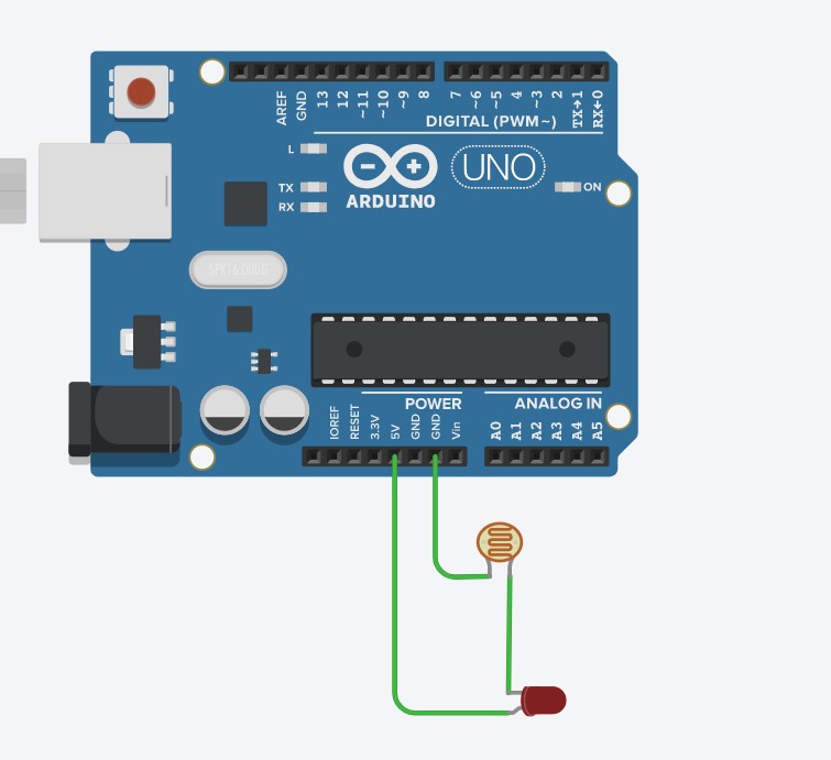
- A photoresistor can be used just like a normal resistor. So, we can connect the LED in series with a resistor.
- To do this, we can connect the cathode of the LED to the photoresistor.
- Then, the photoresistor connects to the GND of the Arduino so that the cathode side of the LED connects to the GND indirectly.
- The anode side of the LED connects to the 5v so that it can receive power.
- And that's it, no code required! Just click on the photoresistor and slide the circle around and see what happens.
Explanation of how it works
- When there is a lot of light hitting the photoresistor, the resistance drops, and so, the current increases throughout the circuit.
- This makes the LED brighter, as more current is passing through it, doing more work.
- When there is less light hitting the photoresistor, there is more resistance, and so current decreases, creating a dimmer LED due to less current passing through it.
- This can be used for things like light detectors for example. Photoresistors can be connected to an analog pin, and so, if there is a lot of voltage, the reading from the analog pin will be higher, indicating more light.
- Programming can be used to detect daytime or night time by setting a range of values that indicate daytime when the value is high enough, or nighttime when the value is low enough.
Last modified 5 years ago
Last modified on Jan 9, 2021, 3:38:15 PM
Attachments (1)
- Photoresistor Circuit.jpg (57.9 KB) - added by 5 years ago.
Download all attachments as: .zip