
Project 1: Making an LED light up

Materials/parts needed
- For this project, you can use either your Arduino kit or TinkerCAD. Note that if you don’t use a high enough resistance for your real life circuit, the LED might stop working permanently.
- Parts needed: Arduino Uno, wires, LED, breadboard, and a 370-500 ohm resistor.
Steps
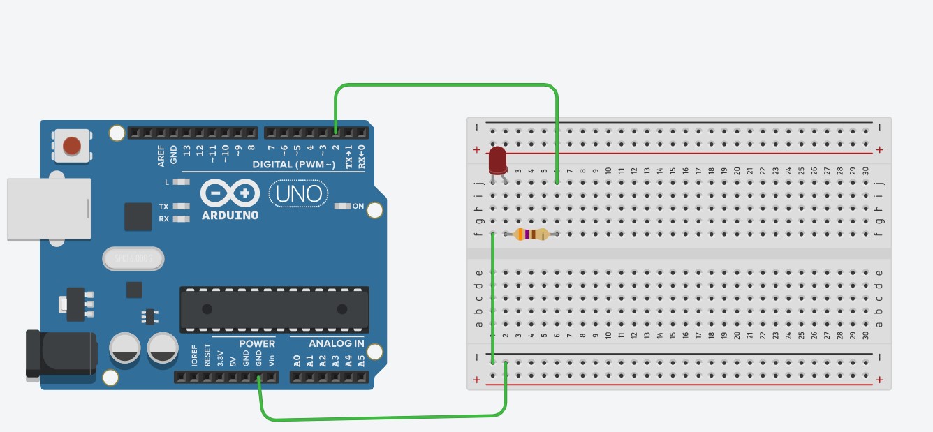
- Once you have all the parts laid out, connect the components together like shown in the picture above, but before you do that, you will need the correct resistance for your resistor.
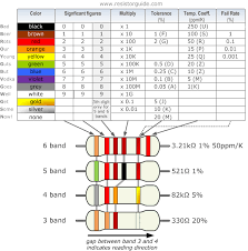
How do you find the correct resistor? You can use this chart to figure out the resistances of the resistors in your kit:

- However, for TinkerCAD, you can just click on the resistor and set the units to ohms (looks like a horseshoe) and type in 370 to get a 370 ohm resistor.
- Notice how the green wire right under the red LED is not close to the lead of the LED, but it is still connected. This is because all the holes on the breadboard in the center (between the black and red colored lines) are connected to each other vertically (in this orientation of the breadboard).
- Another thing is that all the holes next to the black lines are connected to each other, and all the holes next to the red lines are connected to each other by a piece of metal.
LEDs only light up when they are connected so that electricity flows through it in the correct direction. The cathode side of the LED, which is the shorter metal leg, gets connected to the ground of the Arduino. The anode side of the LED, the longer leg, is connected to the digital pins.
- This will require some code, which is provided:
void setup()
{
pinMode(2, OUTPUT);
}
void loop()
{
digitalWrite(2, HIGH);
delay(1000); Wait for 1000 millisecond(s)
digitalWrite(2, LOW);
delay(1000); Wait for 1000 millisecond(s)
}
- Just copy and paste this into the code section of TinkerCAD (its the button next to start simulation, and after that, change the code type to text, and not blocks), or your arduino software (which is found at https://www.arduino.cc/en/software) which you will need to have the arduino connected to your computer by USB to upload the code.
- Finally, press start simulation on TinkerCAD, or press the upload button on your arduino software if you are using the arduino kit.
You should see the LED light up for 1 second, and turn off for 1 second in a repeated fashion.
Explanation of how it works
- Let's follow the trip that an electron takes through your circuit.
- First, it starts at digital pin 2, and is sent off towards the resistor because of our code.
- The resistor is there because it helps to limit the amount of current (how many electrons pass by per second) so that the LED won’t get too much (which is bad).
- The electron then goes through the LED, lighting it up, and travels to the GND, which is what it is attracted to.
Attachments (2)
- Resistor color code.png (9.7 KB) - added by 5 years ago.
- Screenshot 2020-11-18 134219.jpg (130.4 KB) - added by 5 years ago.
Download all attachments as: .zip