
Materials Needed
- You will need: An Arduino, LED(s), a push button, wires, resistors, and a USB cable.
Steps
- This project can be done on both TinkerCAD and with the real Arduino kit.

- Let's start with a resistor that is between 370 and 500 ohms. You can use a resistor chart online (or from the previous projects) to find the ohms of real life resistors. In TinkerCAD, you can just type in the numbers with the correct units.
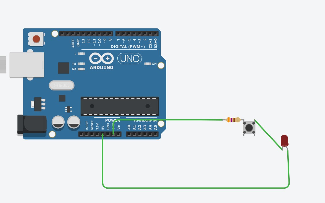
- Next, take out a push button, and connect the resistor to terminal 2a (you can hover over the pins of the push button to see the names). If you are using a real push button, find the side of the push button with a little divot (looks like a square hole made onto the plastic).
- Connect the resistor to that side of the push button with the divot.
- After that, connect the LED’s cathode to the 2b terminal (side without a divot) of the push button.
- Then, connect the resistor to the GND of the Arduino, and the anode of the LED to the 5v of the Arduino.
- And that finishes it! This requires no code as it only needs a power supply, which is in the Arduino. The push button acts as a digital pin in the previous projects, telling when electricity can travel due to making a connection between 2 metal sides of the push button when pressed.
Explanation of how it works
- When the push button is pressed, it makes an electrical connection, creating a path from the 5v to the GND of the Arduino.
- This causes electricity to flow through the resistor (limiting current for the LED) and the LED as well.
- This lights up the LED whenever the push button is pressed.
There is an alternative way to do this.
- Alternatively, you can use code to power the LED whenever the push button is pressed, and this way will also teach you about pull down resistors.

- We’re going to start off with a resistor, that is around 370-500 ohms of resistance. Again, use a resistor chart if you are using a real resistor. If you are using TinkerCAD, just type in the number with the correct units.
- Next, connect that resistor to the anode of the LED (longer leg), and connect the cathode of the LED to the GND next to digital pin 13.
- That finishes the LED part of the circuit, now onto the push button part. Let's start with a resistor. Choose a resistor from 1000 ohms, to 10000 ohms (again use a resistor chart to find the resistance of a real resistor).
- Connect that resistor to the 1b of the push button (side with the divot if you are using a real push button).
- Connect the terminal with the same side with the resistor to digital pin 2.
- By this point, you should have 2 terminal pins on the same side connected to something, and 2 terminal pins not connected to anything, and on the same side as each other.
- Pick a vacant terminal pin and connect that to the 5V of the Arduino.
- Finally, copy and paste the code below into your code option for TinkerCAD, or Arduino software:
const int LED = 13;
const int pushButton = 2;
void setup()
{
pinMode(pushButton, INPUT);
pinMode(LED, OUTPUT);
}
void loop()
{
if (digitalRead(pushButton) == 1){
digitalWrite(LED, HIGH);
}
else{
digitalWrite(LED, LOW);
}
}
Explanation of how it works
- The pushbutton when left open, will leave the terminal pins that are connected to GND, and the digital pin, connected to each other. So, there is only one path between the digital pin and the GND.
- The 5v is left alone on the other side of the push button, so no current is flowing through.
- This makes the digital pin not have any power going to it, so it has a “Low” state, telling the Arduino that the digital pin receives no power. We can use this information in our code to know when to turn on the LED or not.
- Now, when the pushbutton is pressed, it allows the 5v to flow, but to which terminal does the electricity flow to?
- Electricity takes the path of least resistance, and since the path that connects to the digital pin is only a wire, it has no resistance (theoretically), so the electricity flows to the digital pin, making it have a “high” state. On the other hand, the path with the resistor has a lot of resistance in comparison to the path without a resistor, so no electricity flows through there.
- Code can be used to turn on the LED connected to digital pin 13 when power comes into digital pin 2 when the push button is pressed.
- The resistor serves as a barrier, herding the electrons away from the GND pin, and into the digital pin, so that we know when the push button was pressed.
- You might be asking, why can’t we just put the digital pin on 1 side of the push button, and the 5v on the other, and when the push button is pressed, the digital pin gets power?
- If we were to do that, the digital pin will turn on and off randomly even when the push button is left alone. The reason why is because there are a lot of waves of energy happening in the environment, like radio waves, infrared waves, etc, which can enter the push button and give power to the digital pin. We solve this by connecting the wire from the digital pin to GND, and add a resistor connected to GND so that when the push button is pressed, the 5v won’t just travel to GND and totally ignore the digital pin.
Last modified 5 years ago
Last modified on Jan 9, 2021, 3:34:34 PM
Attachments (2)
- Pushbutton Direct.jpg (66.8 KB) - added by 5 years ago.
- Pushbutton with Code.jpg (27.4 KB) - added by 5 years ago.
Download all attachments as: .zip