
Materials Needed
- This project will require the Arduino Kit, or Tinkercad.
- You will need: An Arduino Uno, wires, resistors, LEDs, and a breadboard.
Steps for the Series Circuit
- First, we will be starting off with a series circuit, which is more simple than a parallel circuit.

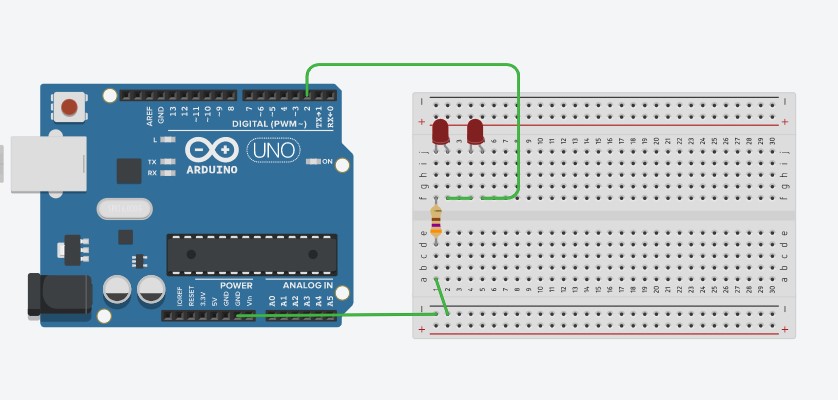
- The series circuit above is just an example of how you can make your circuit, but it is not supposed to be used to directly copy off of, as it might take away from making discoveries, or learning.
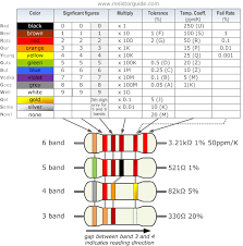
- That being said, we’ll start off with a resistor with a resistance of around 370 to 500 ohms, that connects the top columns of the breadboard, to the bottom columns. Preferably, it should be columns that are directly above/below each other for the sake of organization. Take a moment to think of why we might need this resistor. Below is a chart to help you figure out the resistance of real life resistors. If you are using TinkerCAD, just click on a resistor, change the value to 370 to 500, and the units should be in ohms only (shape looks like a horseshoe).

- Then, place an LED so that the shorter leg of the LED (the metal part of the LED) is connected to the same column that the resistor is connected to, and that the other leg is connected to a column without anything. This allows current to flow from the resistor to the LED.
- Then, you can place 1-2 LEDs near your first LED so that each leg of the LED(s) have their own column that they are connected to, as shown in the picture above.
- In between the LEDs, you will use wires to connect the columns containing the shorter leg (cathode) of 1 LED and connect it to the columns containing the longer leg (anode) of the next LED. Take a look at the picture above if you need a reference.
- Next, there should be 1 LED that has a longer leg (anode) that has an empty column that it is attached to (excluding the LEDs leg).
- This empty column will need to be connected to the digital pin 2, shown in the picture, which is on the “top” of the Arduino.
- Going back to the resistor, look for the column that the resistor is connected to that has nothing else connected to that column. You will be connecting a wire to the GND of the Arduino either directly or indirectly, you can choose whichever method you like.
- The indirect method is the one shown in the picture, where are wire is connected from the column to the row that is next to the black line (signifying negative, as opposed to a red line signifying positive). From there, a wire is connected from that row to the GND of the Arduino. (Note, there are multiple GNDs on an Arduino, you are free to use any one of them).
- The direct method is just to connect a wire from the column with the resistor to the GND of the Arduino.
- After that, the wiring is finished, and now you will need to copy and paste code which is given below. If you are using the Arduino kit, you will need to install the Arduino software at Software | Arduino then plug your Arduino by USB into your computer, copy the code, press verify and upload (found at the top left of the window). If you are using TinkerCAD, press the button that says “Code” look for a button named “Blocks” and switch that to “Text”. Then, delete everything and paste the new code into the area. From there, you can press start simulation.
- Code:
void setup()
{
pinMode(2, OUTPUT);
}
void loop()
{
digitalWrite(2, HIGH);
delay(1000); Wait for 1000 millisecond(s)
digitalWrite(2, LOW);
delay(1000); Wait for 1000 millisecond(s)
}
- Now that you have created your series circuit, it is time to move on to your parallel circuit. You will find that there are some differences, but before you get to that, here’s an explanation of how your series circuit works.
Explanation of how the series circuit works
- If you have done the last project “Making an LED light up”, then you might notice that the series circuit that you just made is very similar to the circuit in the previous project.
- This is because all you did was add a couple more LEDs and connected them one after the other, which is called “in series”.
- Both circuits used a resistor to reduce the current so that the LEDs don’t get too much of it, and both circuits also have the beginning of the circuit start at a digital pin, and end at a GND pin, so that electricity can flow in the first place.
- So, the journey of an electron through your circuit looks like this: It starts off at the digital pin, and is sent off due to the code. It passes through your LEDs, then through your resistor, which has already reduced the current for the whole circuit. Finally, it gets to go to the GND of the Arduino, which is where it is attracted to.
Steps for a Parallel circuit
- If you are using your Arduino kit, you will have to take it apart, and if you are in TinkerCAD, it is recommended to start a new project so that when getting to the code implementation, you won’t get confused on which Arduino to paste the code into.

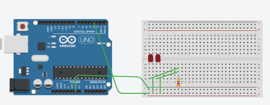
- To start off, place a resistor that has 370 to 500 ohms of resistance (you can use the chart above to help you to find the resistance of a real life resistor) so that 1 end connects to the row that is next to, and follows, the black line. The black line signifies a negative side of a circuit, like a negative side of a battery.
- Next, place 2 LEDs next to each other, so that each leg of the LED has its own column that it is attached to. Keep track of where the longer legs and shorter legs are.
- Then, connect 2 wires to the column that has the resistor. Then, the unconnected sides of those wires will be connected to the columns that have the LEDs’ shorter legs connected to it. Looking at it so far, you might be able to see that the path beginning at the resistor splits off at the 2 wires. This is how a parallel circuit is made, when there is a split in the path so that electrons have multiple paths to “choose” from.
- After that, use wires to make a connection between the columns that have the LEDs’ longer legs and the row that is next to, and follows, the red line, signifying the positive side of the circuit, like a positive of a battery.
- Next, make a connection between digital pin 2, and the row next to the the red line.
- After that, make a connection between the GND of the Arduino, and the row next to the black line.
- Finally, copy the code below into either your Arduino IDE if you are using the Arduino kit, or the “Code” section of the TinkerCAD website (be sure to switch it to the “text” option just as you did for the series circuit portion of the project).
- You should see 2 LEDs start flashing after pressing the start simulation button, or pressed the verify and upload button.
Explanation of how the Parallel Circuit works
- The parallel circuit, unlike the series circuit, splits the circuit into different paths that an electron can take.
- Since current is the amount of electric charge passing by per second, if you were to compare the current at the part of the circuit that hasn’t split off yet, to the part of the circuit that has split off, you will find that the currents of the paths that have split off, will add up to the current of the part that hasn’t split off yet. This is Kirchhoff’s current law.
- So, following the path of an electron, it should look like this: An electron is sent off from digital pin 3, and arrives at the part of the circuit where it splits off. Electrons usually choose/prefer the path of less resistance, but in this situation, there will be an equal amount of electrons in both paths, since both paths have an identical resistance, due to both of them having the same type, and same amount, of LEDs.
- Once the electron goes through one of the paths, it goes through the resistor, which has lowered the current of the entire circuit (including the current inside the paths that split off). It then enters the GND of the Arduino.
Last modified 5 years ago
Last modified on Jan 9, 2021, 3:23:50 PM
Attachments (3)
- Resistor color code.png (9.7 KB) - added by 5 years ago.
- 2 LED Series.jpg (68.9 KB) - added by 5 years ago.
- 2 LED Parallel.jpg (69.9 KB) - added by 5 years ago.
Download all attachments as: .zip