
| Version 14 (modified by , 6 years ago) (diff) |
|---|
Encoders
 In the previous example, we controlled the amount of power we were giving the motor (-1.0=full reverse 0=none, 1.0=full forward), but that doesn't tell us how fast or far the wheel is turning. Just like a car or a bicycle, for a given amount of power, the speed will vary with how heavy the robot is, whether it's going up a hill or down a hill, how good the traction is, etc. To determine how fast a wheel is turning or how much it has turned, we use encoders.
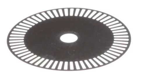
An encoder is a device attached to the motor or wheel shaft that generates a pulse with each partial rotation (e.g. every 1-degree or 5-degrees of rotation, another pulse is generated). By counting these pulses, we can tell how fast the wheel is turning or what position it is in. We can use this information to do things like make a robot travel a fixed distance or at a set speed. You can read more about encoders on ScreenStepsLive.
We connect encoders either directly to RoboRio DIO ports or to an intelligent motor controller such as the TalonSRX. Intelligent motor controllers can use encoder data to offload work from the RoboRIO (e.g. to keep a wheel spinning at a set speed); in general, if you have smart motor controllers, the encoders should connect to them. We'll provide examples both ways:
Encoder connected to RoboRIO DIO (Macademia)
Create another program using the TimedRobot java template and name it EncoderTest. Modify the generated code as follows:
- Add the following imports:
import edu.wpi.first.wpilibj.Encoder;
- Declare a variable for the Encoder in the Robot class
private Encoder leftEncoder;
- • In robotInit() instantiate the Encoder object and reset it
  // Quadrature encoder has A and B channels connected to DIO0, DIO1
  leftEncoder = new Encoder(0, 1);
  // Peanut wheels are 7.5" in diameter
  // Encoders provide 1 count per degree of rotation
  leftEncoder.setDistancePerPulse((3.141592*7.5)/360);
  // reset encoder counts to 0
  leftEncoder.reset();
- In robotPeriodic() read and display the encoder value
  int encoderValue = leftEncoder.getRaw();
  double distance = leftEncoder.getDistance();
  SmartDashboard.putNumber("Encoder Value", encoderValue);
  SmartDashboard.putNumber("Encoder Distance", distance);
For more information and examples of using an encoder connected to DIOs, see the FRC Electrical Bible
Encoder connected to a TalonSRX smart motor controller (Hazelnut)
Create another program using the TimedRobot java template and name it SRXencoderTest. Modify the generated code as follows:
- Add the following imports:
   import com.ctre.phoenix.motorcontrol.can*;
   import com.ctre.phoenix.motorcontrol.FeedbackDevice;
- Declare a variable for the smart motor controller with connected encoder in the Robot class
private WPI_TalonSRX leftMotor;
- • In robotInit() instantiate the motor controller object and reset it
   // TalonSRX is configured with CAN bus address 3
   leftMotor = new WPI_TalonSRX(3);
   // Clear any non default configuration/settings
   leftMotor.configFactoryDefaults();
   // A quadrature encoder is connected to the TalonSRX
   leftMotor.configSelectedFeedbackSensor(FeedbackDevice.QuadEncoder);
- In robotPeriodic() read and display the encoder valuey
SmartDashboard.putNumber("Encoder value", leftMotor.getSelectedSensorPosition());
Note: you'll need to manually turn the left wheel forward and backward to see the Encoder values change. Try turning the wheel 360 degrees to see what value is equivalent to a full revolution of the wheel.
 Notice that the raw count reports the sum of both A and B channels of the quadrature encoder. A quadrature encoder works like the optical encoder shown above, but with two rows of slits in the disk, each slightly offset from the other (overlapping) and each with its own light source/detector. This allows you to determine not just distance and speed but also direction. The light detectors are labeled A and B; because the slots overlap, the sequence of detected light as the wheel rotates forward is: A, AB, B, off, A, AB, etc. When the wheel rotates backwards, the sequence is B, AB, A, off, B, AB, A, off.
You can read more about quadrature encoders here 
Extra credit: ask a mentor to get an oscilloscope so you can see the pulses generated by the encoder as the wheel rotates.
Attachments (4)
-
simple_encoder.jpg (15.9 KB) - added by 6 years ago.
Simple optical encoder
-
Encoder-Working-Principle.gif (93.9 KB) - added by 6 years ago.
OpticalEncoder?
-
encAB.gif (15.8 KB) - added by 6 years ago.
Quadrature AB channels
-
quadEncoder2.gif (17.6 KB) - added by 6 years ago.
Quadrature Encoder
Download all attachments as: .zip